VFD Variable Frequency Drive
When a VFD Variable Frequency Drive is being selected for a specific motor application the first question is “Is it a Variable Torque or a Constant Torque application ?” The short answer is
- VARIABLE TORQUE = All Centrifugal Pump and Fan motor applications
- CONSTANT TORQUE = All other motor applications
Centrifugal Pump operation
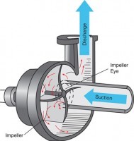
A centrifugal pump and centrifugal fan operate using one principle. They move fluid by creating differential pressure between their inlet and outlet with a spinning impeller. Fluid is drawn into the center (eye) of the impeller and pushed toward the outlet by the differential pressure created when the impeller spins.
Affinity laws define how a centrifugal pump or fan performs from 0-100% speed. They calculate Flow, Pressure and Horsepower at various points on a centrifugal pump curve and a centrifugal fan curve. It’s tough trying to understand centrifugal pump or centrifugal fan curves, but Affinity Laws are simple.
If you were looking to learn more about pumps go to Intro to Pumps
Affinity Laws apply to every centrifugal pump and every centrifugal fan. The laws are simple, but difficult to visualize. They are as follows. When a fixed impeller is spinning at 0-100% Motor Speed, Flow is proportional to Speed, Pressure is the Square of the Speed, and Power is the Cube of the Speed. Below is a table defining them using formulas
Affinity Laws
| MOTOR SPEED (X) | VARIABLE (Y) | FUNCTION TYPE | FUNCTION FORMULA |
| 0-100% | FLOW | LINEAR | (y=x) |
| 0-100% | PRESSURE | SQUARE | (y=x2) |
| 0-100% | HORSEPOWER | CUBE | (y=x3) |
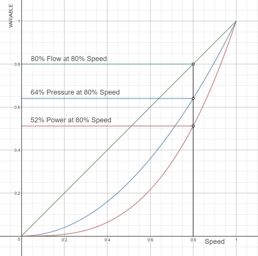
It’s difficult to visualize formulas so let’s look at the curves generated by them. When you see all three curves together the laws become clear and you see something unexpected. When motor speed is reduced, power is reduced faster than flow, so it takes less power per unit flow.
The reduced power per unit of flow becomes energy savings when a Variable Frequency Drive (VFD) is used to reduce motor speed. This becomes significant as the motor size increases.
Centrifugal pump performance example
The chart belows shows at 80% motor speed, centrifugal pump flow is 80%, but the power is 52%.
- AS DESIGNED – When sizing pumps and fans Engineers typically oversize them by >20% for various reasons.
- AS REQUIRED – Users typically only need <80% of designed centrifugal pump or fan flow capacity
- SAVINGS – Users can reduce their energy cost by 35% (1-.52/.80) by reducing motor speed / flow to 80%


